Frequently Asked Questions
Interfaces
User specified data formats can be included. If your Interface isn't listed, please contact us.
Interface to Microsoft Office (WinWord® and Excel®), Google Earth® and FEMFAT analysis.
- RPC®
- Remus®
- Diadem®
- Diadem® - TDM
- Famos®
- nCode
- ASCII
- MSC Adams®
- Simpack®
- Motionsolve®
- Recurdyn®
- VI-Grade®
General
The MBS model should be ready to run including simple tests of functionality like simultaneously/alternating compression of suspension in the full vehicle model.
It is very important to trim the measuring points in MBS with the measurements regarding position, unit and direction with sign.
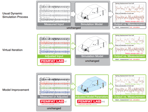
During the VI process, inaccuracies in the model can be identified and corrected with less effort, since the behavior in relation to the measurement data can be analyzed more easily.
If the MBS model seems too inaccurate, FEMFAT LAB model improvement can be used to increase the model accuracy, see following overview
The transfer function consists of many matrices, every frequency step uses one matrix. The quality of the transfer function depends on the noise simulation, therefore all characteristics in the noise is reflected in the transfer function. Generally nonlinearities can be treated with such a transfer function excepted very high ones like (e.g. very stiff bumpstops), here small gains has to be used and therefore the convergence of iteration is slower, sometimes manual editing of inputs is required additionally.
These high nonlinearities should be not included in the transfer function respectively in the noise simulation because otherwise the full time signal (most of it is without these high nonlinearities) will be influenced.
Any tire model can be used, but maybe with loss of accuracy! For an accurate computation of the 3D road, the longitudinal and lateral direction should be also included by e.g. measured wheel centre forces and therefore the tire model should be able to handle these directions.
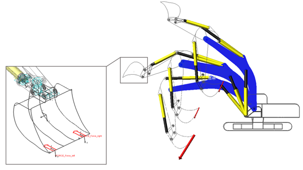
Bucket forces can be computed based on measured cylinder displacements and strains for operation cycles, e.g.:
The following options can be tried regarding the vi process, i.e. without changing the MBS model:
- Modifying the drive manually
- Scale one or more drive channels
- Filter one or more drive channels
- Use different transfer function
- Filter on one or more drive or response channels
- Gain settings, change gain values on drive or response channels
- Modify desired channels for generating new drive but compare your results with original desired channels
Supported model parameters which can be automatically improved:
- Mass, center of gravity
- Mass moment of inertia
- IX or IY or IZ
- Common factor on IX, IY and IZ
- SFORCE
- Stiffness by value or spline, translational (e.g. coil spring) or rotational (e.g. stabilizer stiffness)
- Damping by value or spline, translational or rotational
- VFORCE, GFORCE, FIELD (bushing)
- Stiffness by value or spline, common factor for all directions or directions separately
- Damping by value, common factor for all directions or directions separately
- BEAM
- Planar moment of inertia
- E and G modulus
- Group of elements (e.g. leaf spring)
- Clearance of bumpstop and reboundstop
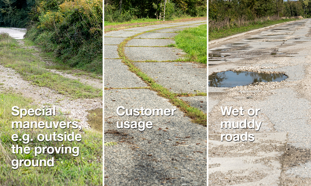
3D road iteration is also able to generate the 3D road for special usages where a scan is not possible:

You have not found what you were looking for and you still have questions?